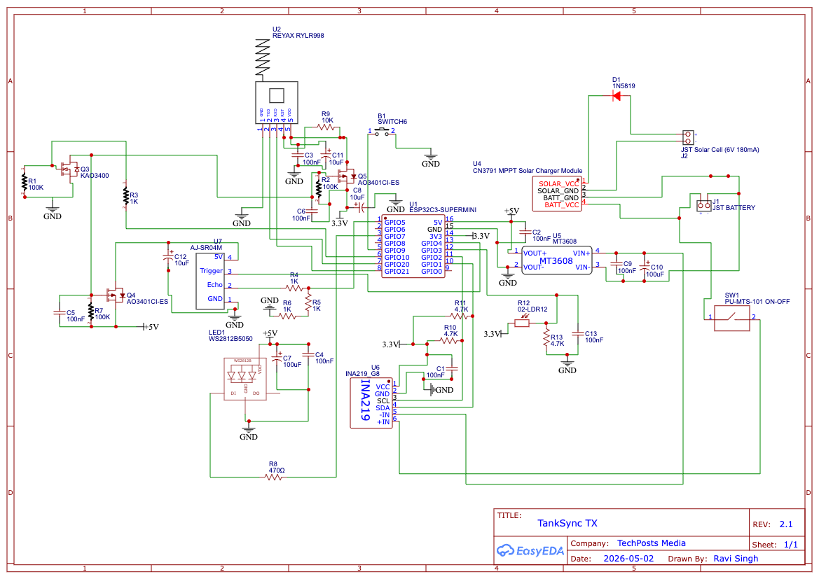
Wiring Reference Transmitter
The TX is a custom circular PCB designed around the ESP32-C3 SuperMini module. RISC-V core, 3.3 V GPIO, not 5 V tolerant — pay attention to the ECHO divider.
Source of truth:
firmware/Transmitter-IDF/main/config.h— if this page disagrees, config.h wins.
Higher-resolution SVG: hardware/pcb/tx-schematic.svg. 3D model for case design: hardware/pcb/tx-pcb-3d.step.
flowchart LR
    Panel[Solar panel<br/>6V 1-2W] --> MPPT[CN3791 MPPT]
    MPPT --> Bat[18650 cell]
    Bat --> Boost[MT3608 3.3V]
    Boost --> C3[ESP32-C3]
All modules share common ground. Vmpp tracks around 4.5 V. Inline Schottky between CN3791 BAT+ and the 18650 (+) — protects against reversed cell insertion. We destroyed two test boards before adding this.
The sensor (JSN-SR04T) needs 5 V. It gets that from the MT3608 boost set to 5 V on a separate output (or via a discrete second boost — depends on PCB rev). The ESP32-C3 sees the ECHO line through a divider because the C3 isn't 5 V tolerant.
| GPIO | Function | Connects to | Direction | Notes |
|---|---|---|---|---|
| GPIO 21 | LORA_TX (UART1) | RYLR998 RXD | Output | 3.3 V logic |
| GPIO 20 | LORA_RX (UART1) | RYLR998 TXD | Input | 3.3 V logic |
| GPIO 4 | Ultrasonic TRIG | JSN-SR04T TRIG | Output | 3.3 V; sensor accepts |
| GPIO 5 | Ultrasonic ECHO | JSN-SR04T ECHO via 1k+2k divider | Input | 5 V echo → 1.65 V at GPIO. Required. |
| GPIO 1 | I²C SDA | INA219 SDA | I/O | INA219 at 0x40
|
| GPIO 2 | I²C SCL | INA219 SCL | Output | — |
| GPIO 0 | Battery ADC (Variant A only) | 100k + 100k divider from VBAT | Analog in | Used only if INA219 absent |
| GPIO 7 | WS2812B data | Status LED chain (2 LEDs) | Output | Works at 3.3 V on most WS2812B |
| GPIO 8 | On-board LED | Built into SuperMini module | Output | Active-high blink patterns |
| GPIO 9 | BOOT button | Tactile button → GND, INPUT_PULLUP | Input | 5 s hold = pairing mode |
Solar (+)        → SS14 Schottky anode
SS14 cathode     → CN3791 IN+
Solar (−)        → CN3791 IN−  → GND
CN3791 BAT+      → 18650 holder (+) via inline Schottky
CN3791 BAT−      → 18650 holder (−) → GND
18650 (+)        → MT3608 IN+
MT3608 OUT (3.3V)→ ESP32-C3 SuperMini 3V3
MT3608 OUT (5V)  → JSN-SR04T VCC
GND (common)     → every module's GND pin
C3 GPIO 21 (TX) → RYLR998 RXD
C3 GPIO 20 (RX) → RYLR998 TXD
3.3 V           → RYLR998 VCC
GND             → RYLR998 GND
Cross TX↔RX. (If pairing never works, suspect a reversed pair before anything else.)
C3 GPIO 4 → JSN-SR04T TRIG
JSN-SR04T ECHO → 1 kΩ → C3 GPIO 5
                 ↓
                2 kΩ → GND   (divider: 5 V ECHO → 1.65 V at GPIO 5)
5 V → JSN-SR04T VCC
GND → JSN-SR04T GND
The sensor cable is field-installable — screw-terminal on the PCB, runs through a cable gland in the enclosure base to the sensor mounted in the tank lid.
C3 GPIO 1 (SDA) → INA219 SDA
C3 GPIO 2 (SCL) → INA219 SCL
3.3 V           → INA219 VCC
GND             → INA219 GND
INA219 VIN+     → 18650 (+) side  (high side, in series with BAT+)
INA219 VIN−     → load side (everything downstream)
Pull-ups on SDA / SCL are 4.7 kΩ on the PCB. If your INA219 breakout already has pull-ups, lift / de-populate the on-PCB ones to avoid double pull-up.
18650 (+) → 100 kΩ → C3 GPIO 0
                 ↓
              100 kΩ → GND
Firmware auto-detects: if INA219 is missing, falls back to Variant A.
C3 GPIO 7 → WS2812B DIN (2 LEDs in series)
C3 GPIO 9 → BOOT button → GND
WS2812B at 3.3 V data line works on most modules but is marginal — if your specific batch is fussy, add a 74AHCT125 level shifter for 5 V data. We've never needed it in practice.
- Reversed UART pair — most "RYLR998 doesn't respond" reports.
- ECHO divider missing — C3 GPIO 5 sees 5 V → C3 ESD diodes get hot → eventually the C3 dies. Don't skip it.
- Battery reversed — was happening pre-Schottky. Now safe. The Schottky drops ~0.3 V which is fine.
- INA219 wrong shunt — must be 0.1 Ω. Some breakouts ship with 0.01 Ω (high-current variant). Wrong shunt → currents off by 10×.
- 5 V sensor on 3.3 V boost — JSN-SR04T runs poorly at 3.3 V (sees short-range only). Use the 5 V boost output.
-
RYLR998
AT\r\n→+OK\r\nwithin 1.5 s → otherwise WS2812 pulses red and the C3 keeps retrying. -
I²C scan
0x40→ switches between INA219 (Variant B) and divider (Variant A) automatically. -
First ultrasonic read — if no echo in 30 ms (= no target inside 5 m), reports
dist=0and the packet includessensor_status='e'— hub interprets that as "sensor error" and shows a warning chip in the PWA.